Axial length and corneal curvature, which affects fundus magnification more?
In the previous post, I hypothesised that a fundus-based DL model would have difficulty predicting the refractive component of ametropia, i.e. that part of refractive error attributable to corneal/ lens curvature. This is due not only to the absence of biologically meaningful features associated with corneal/ lens curvature in fundus images, but also because variation in corneal/ lens curvature gives rise to relatively small variation in fundus magnification. There is little information about corneal/ lens curvature in fundus images, so to speak. I discuss below how I arrived at this conclusion.
Theoretical justification
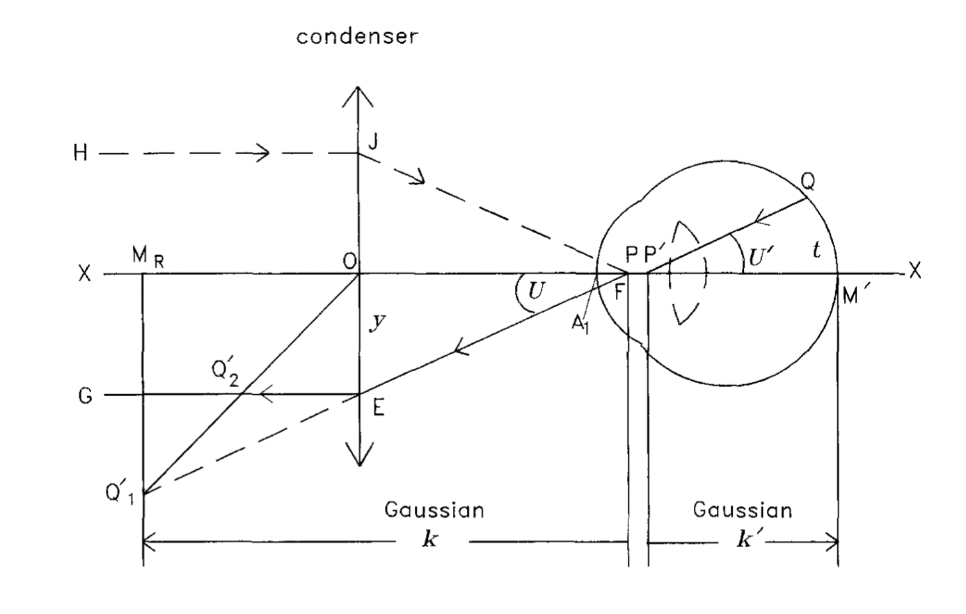
Figure 1: ray diagram depicting a myopic three-surface schematic eye in front of an objective (condenser) lens with telecentric design (taken from Bennett et al. 1994)

About the ray diagram
- the condenser (assuming thin lens) is the lens that is closest to the eye. It is placed in such a way that its primary focal point,
F, coincides with the primary principal point of the eye,P. - Recall that a principal point is where the principal plane (refraction can be said to occur in this plane in a thick/ compound lens system) intersects with the optical axis.
- Hence, any light rays emerging from
P, e.g.FE, will exit the condenser parallel to the optical axis, e.g.EG. Similarly,HJwill converge to pointF. - A light ray emanating from a retinal point,
Q, directed towardsP', will be refracted atP, and ends up as imageQ'1at the far point of the eye, which iskdistance away fromP. PS, far point is by definition the point in space that’s conjugate with the retina when accommodation is relaxed; since the depicted eye is myopic, far point is located at a finite distance (reciprocal of refractive error). Q'1then becomes an object for the condenser. The first construction ray we can use to find where the image will be formed is one that passes through the optical centre,O. The second construction ray isFE(behavior already discussed in 3). The intersection of these two construction rays is where the resultant image,Q'2is formed.
Extra
light ray passing through `O` will not be refracted, since nodal points coincide in a thin lens system. The two principal points also coincide at `O` because the refractive index is similar on both the object and image sides of the lens.
Deriving the equation for total magnification (using Figure 1 as reference)
Total magnification depends on the magnification due to the camera and that due to the optics of an eye. In deriving the equation for total magnification, it is helpful to keep the general equation for magnification, M, in mind:
(1)
where s is image size on the fundus camera film; t is the size of the retinal feature of interest (object).
The following derivation will be based on three assumptions:
- Small-angle approximation of Gaussian optics; that is,
tanθ≈θ; sinθ≈θ; cosθ≈1, where θ is in radian. - Telecentric camera system where the ratio of image size on the camera film,
s, toy(OE; see Figure 1), is a constantpover a wide range of ametropia, such that.
- Gullstrand-Emsley schematic eye is used (see Page 241 of Handbook of Visual Optics). The eye assumes one corneal surface (emmetropic equivalent power = +42.73D) and two lens surfaces (emmetropic equivalent power = +21.3D). The eye also assumes a similar refractive index (n’ = 4/3) for aqueous and vitreous humour.
Let’s first express object size, t
Assuming t is small (which is not an unreasonable assumption), we can use trigonometry:
(2)
Given the small-angle approximation, (2) can be rewritten as:
(3)
Hence:
(4)
Because of the small-angle approximation, we can also rewrite Snell’s Law, , as:
(5)
Considering QP' and PE, n1 is the refractive index of aqeuous/ vitreous humour (1.333), while n2 is the refractive index of air (1.000). Likewise, θ1=U' and θ2=U:
(6)
Substituting (6) into (4):
(7)
U is in radian because the small-angle approximation only works if the unit is radian. Let’s convert it to degree:
(8)
Now express image size, s
We can re-express s from our telecentric assumption:
(9)
where p is a camera-specific constant. It tells us:
How big of a change in
yshould we expect to see a 1-unit change in image size?
Assuming that the distance between the eye p and the condenser is constant (e.g. minimal head movement, etc.), the only variable that could effect y is the angle between the refracted ray (by the eye) and optical axis, U. Hence:
(10)
After re-expressing (10), i.e. `U = s.p, we can substitute the resultant expression into (8):
(11)
Final magnification equation
We can move s to the other side of the equation and arrive at our final equation for magnification, M:
(12)
Since p is a constant, the only variable that affects magnification is K', which is the distance between the secondary principal point of the eye, P', and the centre of the retina. Therefore:
(13)
where AL is axial length and is the distance between the corneal apex and
P'.
It is now obvious that total magnification is dependent on axial length, i.e. the longer the eye (tend to be more myopic), the smaller the magnification.
Total magnification also depends on the position of P’ from the corneal apex, which is in turn dependent on corneal and lens powers.
Axial length affects M to a larger extent
Table 12.6 in the book by Bennett & Rebbetts 1984 shows how changes over a wide range of corneal and lens powers in the Gullstrand-Emsley schematic eye. The table also shows the equivalent power of the eye,
, for each combination of corneal and lens powers. One important observation is:
varies only by a small amount (1.35mm - 2.35mm) over a wide range of corneal-lens power combinations/ refractive ametropia.
Table 1: Column marked with asterisks represents emmetropia in the Gullstrand-Emsley schematic eye. Steps to calculate ametropia are described below.
| Corneal power (D) | +38.00 | +42.73 | +48.00 | ||||||
| Lens power (D) | +15.0 | +21.3 | +29.0 | +15.0 | *+21.3* | +29.0 | +15.00 | +21.30 | +29.00 |
| | +51.24 | +56.20 | +61.60 | +55.65 | *+60.49* | +65.76 | +60.55 | +65.26 | +70.39 |
| | 1.65 | 2.03 | 2.35 | 1.50 | *1.85* | 2.17 | 1.35 | 1.69 | 1.98 |
| Ametropia (D) | +9.24 | +4.28 | -1.12 | +4.83 | *0.00* | -5.28 | -0.07 | -4.78 | -9.91 |
Modelling refractive ametropia using Table 1
We will hold AL constant with a value that would normally give rise to emmetropia and use different combinations of corneal-lens power in Table 1. Emmetropic AL can be found by first calculating k', i.e. distance from P' (because refraction occurs here) to back of the eye:
(14)
Where is the equivalent power of an emmetropic eye;
n' is the refractive index of aqeuous/ vitreous humour; L is the vergence of the incident light from an object located at the far point. L is 0 in an emmetropic eye because its far point is at inifinity. Thus, solving the following equation:
gives us k'= 22.04mm.
AL is simply +
k'= 22.04mm + 1.85mm (Table 1) = 23.89mm.
We can then repurpose equation (14) to calculate (refractive) ametropia, i.e. solve for L, resulting from a range of corneal-lens power combinations:
(15)
We can finally calculate the total magnification associated with each level of ametropia using equation (12). Note that AL is kept constant, i.e. 23.89mm, across all levels of ametropia for the calculation so we can be sure that only a change in — as brought about by variation in corneal/lens power — affects magnification.
Modelling axial ametropia using Table 1
To level the playing field, the AL equivalent of each corneal-lens power combination is first computed. This is done by using the corneal-lens power combination that would normally result in emmetropia (+42.73D & +21.30D) and varying only AL such that the magnitude of resultant (axial) ametropia matches that of refractive ametropia:
Where = 60.49D (resulting from emmetropic corneal-lens power combination as per Table 1),
ammetropia matches a given level of refractive ammetropia computed from (15); 0.00185 represents the emmetropic (see Table 1) expressed in m.
Total magnification for each level of axial myopia can then be computed using equation (12) — holdingk' constant at 0.00185m, since corneal and lens powers remain constant under current assumption of axial ametropia. The camera magnification constant, p, is assumed to be 1.37 (West German Zeiss fundus camera used by Littmann 1982).
Total magnification across a wide range of axial and refractive ametropia
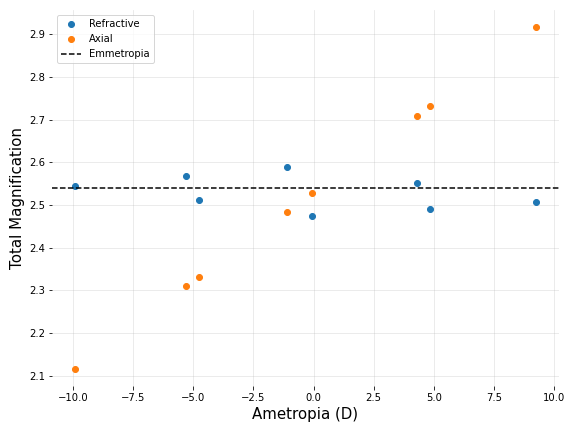
Figure two compares the total magnification between similar levels of axial and refractive ametropia. Total magnification (2.54) arising from an emmetropic eye is represented by a dotted black line.
Figure 2: Total magnification across a wide range of axial and refractive ametropia. Note that 0.0D datapoint is -0.07D in reality (rounding error); hence, the corresponding magnification does not coincide with the emmetropic line (true 0.0D)

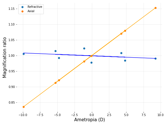
Figure 3: Magnification ratio, i.e. ametropic magnification / emmetropic magnification, vs Ametropia. Similar to Figure 2, 0.0D datapoint is -0.07D in reality due to rounding error.

It is obvious from both figures that the total magnification resulting from refractive ametropia varies little from that seen in emmetropia. This is because there’s very little variation in across a wide range of refractive ametropia (as pointed out earlier). Conversely, there is a clear positive correlation between total magnification and axial ametropia. Therefore:
A hypothetical DL model — if were to only rely on fundus magnification — would (theoretically) fail to predict the amount of ametropia when it is purely corneal/lenticular in nature.